Tuesday, June 17, 2014

Internetworking with TCP/IP Notes (Chapter 2)

Chapter 2 Overview of underlying Network Technologies

2.1 Two Approaches to Network Communication

2.1.1 Connection Oriented (Circuit Switched)
Connection-oriented networks operate by forming a dedicated connection or circuit between two points That is, once a circuit is established, no other network activity will decrease the capacity of the circuit. One disadvantage of connection-oriented technology arises from cost: circuit costs are fixed, independent of use.

2.1.2 Connectionless  (Packet Switched)
In a connectionless system, data to be transferred across a network is divided into small pieces called packets that are multiplexed onto high capacity inter machine connections. The chief advantage of packet-switching is that multiple communications among computers can proceed concurrently, with inter-machine connections shared by all pairs of computers that are communicating. The disadvantage, of course, is that as activity increases, a given pair of communicating computers receives less of the network capacity. 

Despite the potential drawback of not being able to guarantee network capacity, connectionless networks have become extremely popular. The chief motivations for adopting packet switching are cost and performance.


2.2 Hardware Addressing Schemes 

Internet protocols must handle one particular aspect of network hardware: heterogeneous addressing schemes. Each network hardware technology defines an addressing mechanism that computers use to specify the destination for a packet. A packet sent across a network includes two addresses: a destination address that specifies the intended recipient, and a source address that specifies the sender. 

2.3 Ethernet (IEEE 802.3)


2.3.1 Automatic Negotiation

The important aspect of multi-speed Ethernet lies in automated configuration. When a cable is plugged in, both ends enter a negotiation phase. The negotiation determines the type of cable (straight through or cross-over) and the maximum speed that the other side of the connection can support.

Autonegotiation works by sending eletrical pulses. In 10Base-T these are called Normal Link Pulses (NLP). They are sent every 16th ms with a tolerance of 8 ms. They are only sent when the Network Interface Card (NIC) is not receiving or sending traffic. They look like this:
In the fast Ethernet standard (802.3u) these are called Fast Link Pulses (FLP) and they look like this:
These electrical pulses lets us determine the speed and duplex mode that is available in autonegotiation. The priority for choosing a speed and duplex mode goes like this:
  • 1000Base-T – Full duplex
  • 1000Base-T - Half duplex
  • 100Base-T2 – Full duplex
  • 100Base-TX – Full duplex
  • 100Base-T2 – Half duplex
  • 100Base-T4
  • 100Base-TX – Half duplex
  • 10BaseT – Full duplex
  • 10BaseT – Half duplex
If one side is set to auto and the other side hardcoded parallell detection kicks in. Parallell detection can determine the speed by looking at the format of the electrical pulses it is receiving from its link partner. Duplex can’t be detected so that will default to half duplex. This is why we sometimes see links with 100/half duplex. If one side is auto and the other 100/full the auto side will be set to 100/half.
2.3.2 Important Properties of Ethernet
Broadcast Capability. Ethernet supports broadcast, which means a sender can
specify that a given packet should be delivered to all computers that are attached to the
network.  We will see that TCP/IP depends on Ethernet broadcast.
Best-Effort Delivery Semantics. Ethernet uses best-effort delivery semantics, which means that the network tries to deliver packets, the hardware does not guarantee delivery and does not inform a sender if the packet cannot be delivered.

2.3.3 48-Bit Ethernet MAC (Hardware) Addresses

An Ethernet address is assigned to a network interface card, not to acomputer
The IEEE 48-bit MAC addressing scheme provides three types of addresses:
  • Unicast
  • Broadcast
  • Multicast
2.3.4 Ethernet Frame Format and Packet Size
There are several types of Ethernet frames:
  • Ethernet II frame, or DIX. It is the most common type in use today, as it is often used directly by the Internet Protocol.
  • IEEE 802.2 Logical Link Control (LLC) frame
  • IEEE 802.2 Subnetwork Access Protocol (SNAP) frame
The different frame types have different formats and MTU values, but can coexist on the same physical medium. Differentiation between frame types is possible based on the below table.
In addition, all four Ethernet frames types may optionally contain an IEEE 802.1Q tag to identify what VLAN it belongs to and its priority (quality of service). This encapsulation is defined in the IEEE 802.3ac specification and increases the maximum frame by 4 octets.
2.3.4.1 Ethernet II 
Ethernet frames are variable length, with no frame smaller than 64 octets or larger than 1514 octets (header and data). When transmitted, the frame also includes a 4-octet Cyclic Redundancy Check (CRC) that is used to check for transmission errors. Because the CRC field is added by the sending hardware and checked by the receiving hardware, the CRC is not visible to higher layers of protocol software.

Take a  look at an Ethernet frame:
The preamble is a pattern of alternating ones and zeroes and ending with two ones
The preamble field won’t show up in a packet capture since the network card will already have stripped it before it’s available for capture. The preamble field contains a synchronization pattern that consists of alternating ones and zeros and ends with two consecutive ones. It is used to synchronize node communication but also to indicate where the frame start. Because it is not processed in the same way as the rest of the frame we do not have to count the eight bytes of preamble when calculating Ethernet frame size. This is what preamble looks like:
1010101010101010101010101010101010101010101010101010101010101011
The source and destination MAC is used for switching based on the MAC.
The EtherType field specifies that upper level protocol. Some of the most well known ones are:
0×0800 – IP
0×8100 – 802.1Q tagged frame
0×0806 – ARP
0x86DD – IPv6
After that follow the actual payload which should be between 46 – 1500 bytes in size.
In the end there is a Frame Checking Sequence (FCS) which is used to check the validity of the frame. If the CRC check fails the frame is dropped.
In total the frame will be maximum 1514 bytes or 1518 if counting the FCS.
2.3.4.2 IEEE 802.3 with LLC Header
When it comes to 802.3 Ethernet there are actually two frame formats. One is 802.3 with 802.2 LLC SAP header. It looks like this.
This was the original version from the IEEE. Many of the fields are the same. Let’s look at those that are not.
The preamble is now divided in preamble and Start Frame Delimiter (SFD) but the function is the same.
The length field is used to indicate how many bytes of data are following this field before the FCS. It can also be used to distinguish between DIX frame and 802.3 frame as for DIX the values in this field will be higher e.g. 0×806 for ARP. If this value is greater than 1536 (0×600 Hex) then it is a DIX frame and the value is an Ethertype value. The length cannot be bigger than 1500 as the maximum size of frame is 1500.

* Hexadecimal 0x600 = 1536 ( 0 x 16^3 + 6 x 16^2 + 0 x 16^1 + 0 x 16^0)
http://www.cavestory.org/guides/csasm/guide/hex2.html
Then we have some interesting values called DSAP, SSAP and Control. SAP stands for Service Access Point, the S and D in SSAP and DSAP stands for source and destination.
They have a similar function as the Ethertype. The SAP is used to distinguish between different data exchanges on the same station. The SSAP indicates from which service the LLC data unit was sent and the DSAP indicates the service to which the LLC data unit is being sent. IP has a SAP of 6 and 802.1D (STP) has a SAP of 42. It would be very strange to have a different SSAP and DSAP so these values should be the same. IP to IP would be SSAP of 06 and DSAP of 06. One bit (LSB) in the DSAP is used to indicate if it is a group address or an individual address. If it is set to zero it refers to an individual address going to a Local SAP (LSAP). One bit in the SSAP (LSB) indicates if it is a command or response packet. That leaves us with 64 possible different SAPs for SSAP and DSAP.
The contol field is used to select if communication should be connection-less or connection-oriented. Usually error recovery and flow control are performed by higher level services such as TCP.
2.3.4.3 IEEE 802.3 with SNAP Header
The IEEE had problems to address all the layer 3 processes due to the short DSAP and SSAP fields in the header. This is why they introduced a new frame format called Subnetwork Access Protocol (SNAP). Basically this header is using the type field found in the DIX header. If the SSAP and DSAP is set to 0xAA and the Control field is set to 0×03 then SNAP encapsulation will follow. SNAP has a five byte extension to the standard 802.2 LLC header and it consists of a 3 byte OUI and a two byte Type field.
From a vendor perspective this is good because then they can have an OUI and then create their own types to use. If we look at PVST+ BPDUs from a Cisco device we will see that they are SNAP encapsulated where the organization code is Cisco (0x00000c) and the PID is PVSTP+ (0x010b). CDP is also using SNAP and it has a PID of CDP (0×0200). I will talk more about BPDUs and STP in a following post but first I wanted to provide the background on the Ethernet frame types used.
In summary there are three different Ethernet frame types used. DIX frame, also called Ethernet II, IEEE 802.3 with LLC and IEEE 802.3 with SNAP encapsulation. There are others out there as well but these are the three major ones and the DIX one is by far the most common one.

2.4 Zigbee (IEEE 802.15.4)
IEEE has created standard 802.15.4 for a low-power wireless network technology intended to support connections of small embedded devices. The low-power aspect makes 802.15.4 radios attractive for devices that run on battery power. The packet size is 127 octets, but only 102 octets are available for a payload.

2.5 Optical Carrier and Packet Over SONET (OC, POS)

The data rates of available circuits have been chosen to carry multiples of 64 Kbps because a digitized voice call uses an encoding known as Pulse Code Modulation(PCM) which produces 8000 samples per second, where each sample is 8 bits. Thus, it is 8000x8bits = 64kb.
Higher-rate digital circuits require the use of fiber. Figure below lists examples of Optical Carrier(OC) standards and the data rate of each. A suffix on “OC” denotes a capacity.
2.6 Point-to-Point Networks
If the communication system connects exactly two endpoints, it 
is known as a point-to-point network. Thus, a leased data circuit is an example of a point-to-point network. Dialup provides an example of a point-to-point network.

Internetworking with TCP/IP Notes (Chapter 1)

Chapter 1  Introduction and Overview

1.1 Application Level Internet Services

* WWW
* Cloud Access & Remote Desktop
* File Transfer
* Email
* Voice & Video Services

1.2 Network Level Internet Services
* Connectionless Packet Delivery Service

* Reliable Stream Transport Service

1.3 Distinguish between TCP/IP services from others

* Network Technology Independence
* Universal Interconnection
* End-to-End Acknowledgements 
* Application Protocol Standards

Berkeley UNIX created a new operating system abstraction known as a socket to allow applications to access the Internet protocols. A generalization of the UNIX mechanism for I/O, the socket interface has options for other network protocols besides TCP/IP. The introduction of the socket abstraction was important because it allowed programmers to use TCP/IP protocols with little effort.

1.4 Internet Request For Comments (RFCs)
The documentation of protocols, standards, and policies cannot be obtained from a vendor and the IETF manages the standardization process. The resulting protocol documents are kept in an on-line repository and made available at no charge.

1.5 Changes from IPv4 to IPv6
Despite conceptual similarities, IPv6 changes most of the protocol details. The changes introduced by IPv6 can be grouped into seven categories:

Larger Addresses. The new address size is the most noticeable change. IPv6 quadruples the size of an IPv4 address from 32 bits to 128 bits.

Extended Address Hierarchy. IPv6 uses the larger address space to create additional levels of addressing hierarchy 

New Header Format. IPv6 uses an entirely new and incompatible packet format that includes a set of optional headers.

Improved Options. IPv6 allows a packet to include optional control information not available in IPv4.

Provision For Protocol Extension. Instead of specifying all details, the IPv6 extension capability allows the IETF to adapt the protocol to new network hardware and new applications.

Support For Auto-configuration And Renumbering. IPv6 allows a site to change from one ISP to another by automating the requisite address changes.

Support For Resource Allocation. IPv6 includes a flow abstraction and allows differentiated services

1.6 Dual Stack System
Dual-stack systems allow applications to choose whether they will use IPv4, IPv6, or both. Older applications continue to use IPv4. However, a dual-stack mechanism allows an application to choose dynamically, making migration automatic. 

Friday, May 30, 2014

VXLAN Overview
As its name indicates, VXLAN is designed to provide the same Ethernet Layer 2 network services as VLAN does today, but with greater extensibility and flexibility. Compared to VLAN, VXLAN offers the following benefits:
• Flexible placement of multitenant segments throughout the data center: It provides a solution to extend Layer 2 segments over the underlying shared network infrastructure so that tenant workload can be placed across physical pods in the data center.
• Higher scalability to address more Layer 2 segments: VLANs use a 12-bit VLAN ID to address Layer 2 segments, which results in limiting scalability of only 4094 VLANs. VXLAN uses a 24-bit segment ID known as the VXLAN network identifier (VNID), which enables up to 16 million VXLAN segments to coexist in the same administrative domain.
• Better utilization of available network paths in the underlying infrastructure: VLAN uses the Spanning Tree Protocol for loop prevention, which ends up not using half of the network links in a network by blocking redundant paths. In contrast, VXLAN packets are transferred through the underlying network based on its Layer 3 header and can take complete advantage of Layer 3 routing, equal-cost multipath (ECMP) routing, and link aggregation protocols to use all available paths.
VXLAN Encapsulation and Packet Format
VXLAN is a Layer 2 overlay scheme over a Layer 3 network. It uses MAC Address-in-User Datagram Protocol (MAC-in-UDP) encapsulation to provide a means to extend Layer 2 segments across the data center network. VXLAN is a solution to support a flexible, large-scale multitenant environment over a shared common physical infrastructure. The transport protocol over the physical data center network is IP plus UDP.
VXLAN defines a MAC-in-UDP encapsulation scheme where the original Layer 2 frame has a VXLAN header added and is then placed in a UDP-IP packet. With this MAC-in-UDP encapsulation, VXLAN tunnels Layer 2 network over Layer 3 network. The VXLAN packet format is shown in Figure 1.
Figure 1. VXLAN Packet Format
As shown in Figure 1, VXLAN introduces an 8-byte VXLAN header that consists of a 24-bit VNID and a few reserved bits. The VXLAN header together with the original Ethernet frame goes in the UDP payload. The 24-bit VNID is used to identify Layer 2 segments and to maintain Layer 2 isolation between the segments. With all 24 bits in VNID, VXLAN can support 16 million LAN segments.
VXLAN Tunnel Endpoint
VXLAN uses VXLAN tunnel endpoint (VTEP) devices to map tenants' end devices to VXLAN segments and to perform VXLAN encapsulation and de-encapsulation. Each VTEP function has two interfaces: One is a switch interface on the local LAN segment to support local endpoint communication through bridging, and the other is an IP interface to the transport IP network.
The IP interface has a unique IP address that identifies the VTEP device on the transport IP network known as the infrastructure VLAN. The VTEP device uses this IP address to encapsulate Ethernet frames and transmits the encapsulated packets to the transport network through the IP interface. A VTEP device also discovers the remote VTEPs for its VXLAN segments and learns remote MAC Address-to-VTEP mappings through its IP interface. The functional components of VTEPs and the logical topology that is created for Layer 2 connectivity across the transport IP network is shown in Figure 2.
Figure 2. VTEP
The VXLAN segments are independent of the underlying network topology; conversely, the underlying IP network between VTEPs is independent of the VXLAN overlay. It routes the encapsulated packets based on the outer IP address header, which has the initiating VTEP as the source IP address and the terminating VTEP as the destination IP address.
VXLAN Packet Forwarding Flow
VXLAN uses stateless tunnels between VTEPs to transmit traffic of the overlay Layer 2 network through the Layer 3 transport network. An example of a VXLAN packet forwarding flow is shown in Figure 3.
Figure 3. VXLAN Unicast Packet Forwarding Flow
In Figure 3, Host-A and Host-B in VXLAN segment 10 communicate with each other through the VXLAN tunnel between VTEP-1 and VTEP-2. This example assumes that address learning has been done on both sides, and corresponding MAC-to-VTEP mappings exist on both VTEPs.
When Host-A sends traffic to Host-B, it forms Ethernet frames with MAC-B address of Host-B as the destination MAC address and sends them out to VTEP-1. VTEP-1, with a mapping of MAC-B to VTEP-2 in its mapping table, performs VXLAN encapsulation on the packets by adding VXLAN, UDP, and outer IP address header to it. In the outer IP address header, the source IP address is the IP address of VTEP-1, and the destination IP address is the IP address of VTEP-2. VTEP-1 then performs an IP address lookup for the IP address of VTEP-2 to resolve the next hop in the transit network and subsequently uses the MAC address of the next-hop device to further encapsulate the packets in an Ethernet frame to send to the next-hop device.
The packets are routed toward VTEP-2 through the transport network based on their outer IP address header, which has the IP address of VTEP-2 as the destination address. After VTEP-2 receives the packets, it strips off the outer Ethernet, IP, UDP, and VXLAN headers, and forwards the packets to Host-B, based on the original destination MAC address in the Ethernet frame.
VXLAN Implementation on Cisco Nexus 9000 Series Switches
Cisco Nexus 9000 Series Switches support the hardware-based VXLAN function that extends Layer 2 connectivity across the Layer 3 transport network and provides a high-performance gateway between VXLAN and non-VXLAN infrastructures. The following sections provide the details of VXLAN implementation on Cisco Nexus 9000 Series Switches in NX-OS mode.
Layer 2 Mechanisms for Broadcast, Unknown Unicast, and Multicast Traffic
VXLAN on Cisco Nexus 9000 Series Switches uses existing Layer 2 mechanisms - flooding, and dynamic MAC address learning - to do the following:
• Transport broadcast, unknown unicast, and multicast traffic
• Discover remote VTEPs
• Learn remote host MAC addresses and MAC-to-VTEP mappings for each VXLAN segment
For these traffic types, IP multicast is used to reduce the flooding scope of the set of hosts that are participating in the VXLAN segment.
Each VXLAN segment, or VNID, is mapped to an IP multicast group in the transport IP network. Each VTEP device is independently configured and joins this multicast group as an IP host through the Internet Group Management Protocol (IGMP). The IGMP joins trigger Protocol Independent Multicast (PIM) joins and signaling through the transport network for the particular multicast group. The multicast distribution tree for this group is built through the transport network based on the locations of participating VTEPs. The multicast tunnel of a VXLAN segment through the underlying IP network is shown in Figure 4.
Figure 4. VXLAN Multicast Group in Transport Network
This multicast group shown in Figure 4 is used to transmit VXLAN broadcast, unknown unicast, and multicast traffic through the IP network, limiting Layer 2 flooding to those devices that have end systems participating in the same VXLAN segment. VTEPs communicate with one another through the flooded or multicast traffic in this multicast group.
Remote VTEP Discovery and Tenant Address Learning
The Cisco Nexus 9000 VXLAN implementation uses the classic Layer 2 data plane flooding and learning mechanisms for remote VTEP discovery and tenant address learning. The network in Figure 4 is an example that shows the learning process.
The tenant VXLAN segment has VNID 10 and uses the multicast group 239.1.1.1 over the transport network. It has three participating VTEPs in the data center. Assume that no address learning has been performed between locations. End System A (with IP-A, MAC-A) starts IP communication with End System B (with IP-B, MAC-B). The sequence of steps is shown in Figure 5.
Figure 5. VXLAN Peer Discoveries and Tenant Address Learning
1. End System A sends out an Address Resolution Protocol (ARP) request for IP-B on its Layer 2 VXLAN network.
2. VTEP-1 receives the ARP request. It does not yet have a mapping for IP-B. VTEP-1 encapsulates the ARP request in an IP multicast packet and forwards it to the VXLAN multicast group. The encapsulated multicast packet has the IP address of VTEP-1 as the source IP address and the VXLAN multicast group address as the destination IP address.
3. The IP multicast packet is distributed to all members in the tree. VTEP-2 and VTEP-3 receive the encapsulated multicast packet because they've joined the VXLAN multicast group.
They de-encapsulate the packet and check its VNID in the VXLAN header. If it matches their configured VXLAN segment VNID, they forward the ARP request to their local VXLAN network. They also learn the IP address of VTEP-1 from the outer IP address header and inspect the packet to learn the MAC address of End System A, placing this mapping in the local table.
4. End System B receives the ARP request forwarded by VTEP-2. It responds with its own MAC address (MAC-B), and learns the IP-A-to-MAC-A mapping.
5. VTEP-2 receives the ARP reply of End System B that has MAC-A as the destination MAC address. It now knows about MAC-A-to-IP-1 mapping. It can use the unicast tunnel to forward the ARP reply back to VTEP-1. In the encapsulated unicast packet, the source IP address is IP-2 and the destination IP address is IP-1. The ARP reply is encapsulated in the UDP payload.
6. VTEP-1 receives the encapsulated ARP reply from VTEP-2. It de-encapsulates and forwards the ARP reply to End System A. It also learns the IP address of VTEP-2 from the outer IP address header and inspects the original packet to learn MAC-B-to-IP-2 mapping.
7. Subsequent IP packets between End Systems A and B are unicast forwarded, based on the mapping information on VTEP-1 and VTEP-2, using the VXLAN tunnel between them.
8. VTEP-1 can optionally perform proxy ARPs for subsequent ARP requests for IP-B to reduce the flooding over the transport network.
ECMP and LACP Load Sharing with VXLAN
Encapsulated VXLAN packets are forwarded between VTEPs based on the native forwarding decisions of the transport network. Most of the data center transport networks are designed and deployed with multiple redundant paths and take advantage of various multipath load-sharing technologies to distribute traffic loads on all available paths. It is desirable to share the load of the VXLAN traffic in the same fashion in the transport network.
A typical VXLAN transport network is an IP-routing network that uses the standard IP ECMP to balance the traffic load among multiple best paths. To avoid out-of-sequence packet forwarding, flow-based ECMP is commonly deployed. An ECMP flow is defined by the source and destination IP addresses and optionally the source and destination TCP or UDP ports in the IP packet header.
Because all the VXLAN packet flows between a pair of VTEPs have the same outer source and destination IP addresses, and all VTEP devices must use one identical destination UDP port that can be either the Internet Allocated Numbers Authority (IANA)-allocated UDP port 4789 or a customer-configured port, the only variable element in the ECMP flow definition that can differentiate VXLAN flows from the transport network standpoint is the source UDP port. A similar situation for Link Aggregation Control Protocol (LACP) hashing occurs if the resolved egress interface based on the routing and ECMP decision is an LACP port channel. The LACP uses the VXLAN outer-packet header for link load-share hashing, which results in the source UDP port being the only element that can uniquely identify a VXLAN flow.
Cisco Nexus 9000 Series Switches implement VXLAN in the way that a hash of the inner frame's header is used as the VXLAN source UDP port. As a result, a VXLAN flow can be unique, with the IP addresses and UDP ports combination in its outer header while traversing the underlay transport network. Therefore, the hashed source UDP port introduces a desirable level of entropy for ECMP and LACP load balancing.
Cisco Nexus 9000 as Hardware-Based VXLAN Gateway
VXLAN is a new technology for virtual data center overlays and is being adopted in data center networks more and more, especially for virtual networking in the hypervisor for virtual machine-to-virtual machine communication. However, data centers are likely to contain devices that are not capable of supporting VXLAN, such as legacy hypervisors, physical servers, and network services appliances, such as physical firewalls and load balancers, and storage devices, etc. Those devices need to continue to reside on classic VLAN segments. It is not uncommon that virtual machines in a VXLAN segment need to access services provided by devices in a classic VLAN segment. This type of VXLAN-to-VLAN connectivity is enabled by using a VXLAN gateway.
A VXLAN gateway is a VTEP device that combines a VXLAN segment and a classic VLAN segment into one common Layer 2 domain. The logic mapping between IEEE 802.1Q VLAN and VXLAN on a VXLAN gateway is shown in Figure 6.
Figure 6. VXLAN-to-VLAN Logic Mapping by VXLAN Gateway
A Cisco Nexus 9000 Series Switch can function as a hardware-based VXLAN gateway. It seamlessly connects VXLAN and VLAN segments as one forwarding domain across the Layer 3 boundary without sacrificing forwarding performance. The Cisco Nexus 9000 Series eliminates the need for an additional physical or virtual device to be the gateway. The hardware-based encapsulation and de-encapsulation provides line-rate performance for all frame sizes. Examples of Cisco Nexus 9000 Series Switches as VXLAN gateways are shown in Figure 7.
Figure 7. Cisco Nexus 9000 as VXLAN Gateways
Network Considerations for Common VXLAN Deployments
MTU Size in the Transport Network
Due to the MAC-to-UDP encapsulation, VXLAN introduces 50-byte overhead to the original frames. Therefore, the maximum transmission unit (MTU) in the transport network needs to be increased by 50 bytes. If the overlays use a 1500-byte MTU, the transport network needs to be configured to accommodate 1550-byte packets at a minimum. Jumbo-frame support in the transport network is required if the overlay applications tend to use larger frame sizes than 1500 bytes.
ECMP and LACP Hashing Algorithms in the Transport Network
As described in a previous section, Cisco Nexus 9000 Series Switches introduce a level of entropy in the source UDP port for ECMP and LACP hashing in the transport network. As a way to augment this implementation, the transport network uses an ECMP or LACP hashing algorithm that takes the UDP source port as an input for hashing, which achieves the best load-sharing results for VXLAN encapsulated traffic.
Multicast Group Scaling
The VXLAN implementation on Cisco Nexus 9000 Series Switches uses multicast tunnels for broadcast, unknown unicast, and multicast traffic forwarding. Ideally, one VXLAN segment mapping to one IP multicast group is the way to provide the optimal multicast forwarding. It is possible, however, to have multiple VXLAN segments share a single IP multicast group in the core network.
VXLAN can support up to 16 million logical Layer 2 segments, using the 24-bit VNID field in the header. With one-to-one mapping between VXLAN segments and IP multicast groups, an increase in the number of VXLAN segments causes a parallel increase in the required multicast address space and the amount of forwarding states on the core network devices. At some point, multicast scalability in the transport network can become a concern. In this case, mapping multiple VXLAN segments to a single multicast group can help conserve multicast control plane resources on the core devices and achieve the desired VXLAN scalability. However, this mapping comes at the cost of suboptimal multicast forwarding. Packets forwarded to the multicast group for one tenant are now sent to the VTEPs of other tenants that are sharing the same multicast group. This causes inefficient utilization of multicast data plane resources. Therefore, this solution is a trade-off between control plane scalability and data plane efficiency.
Despite the suboptimal multicast replication and forwarding, having multiple-tenant VXLAN networks to share a multicast group does not bring any implications to the Layer 2 isolation between the tenant networks. After receiving an encapsulated packet from the multicast group, a VTEP checks and validates the VNID in the VXLAN header of the packet. The VTEP discards the packet if the VNID is unknown to it. Only when the VNID matches one of the VTEP's local VXLAN VNIDs, does it forward the packet to that VXLAN segment. Other tenant networks will not receive the packet. Thus, the segregation between VXLAN segments is not compromised.
Conclusion
VXLAN provides a solution to extend Layer 2 networks across Layer 3 infrastructure by way of MAC-in-UDP encapsulation and tunneling. VXLAN enables flexible workload placements by way of the Layer 2 extension. It is also an approach to building a multitenant data center by decoupling tenant Layer 2 segments from the shared transport network.
Virtualized hosts are increasingly adopting VXLAN; however, it is rare to have a completely virtualized environment in a data center. More commonly, a data center has coexisting virtual machines, bare-metal hosts, and physical service appliances. Virtual machines need to access services on physical hosts and appliances, which creates the need of a gateway for virtual machines in a VXLAN segment to communicate with devices in a classic VLAN segment.
Cisco Nexus 9000 Series Switches support VXLAN functions with hardware-based performance. Deployed as a VXLAN gateway, Cisco Nexus 9000 Series Switches easily connect VXLAN and classic VLAN segments to create a common forwarding domain so that tenant devices can flexibly reside in both environments with virtually one-hop connectivity. In contrast to software-based VXLAN gateway solutions, Cisco Nexus 9000 Series Switches provide line-rate performance in hardware, which is critical to ensuring the performance of applications that involves devices in both VXLAN and VLAN networks.
For More Information

http://blogs.vmware.com/vsphere/2013/04/vxlan-series-different-components-part-1.html

Friday, May 23, 2014

IP Fragmentation

Originated from Daniels Networking Blog
Every physical medium has a maximum size of packets it can send. This is called MTU (Maximum Transmission Unit). For Ethernet this is usually 1500 bytes. If we send packets that are larger than 1500 bytes fragmentation is needed. Fragmentation is the method of dividing one large packet into several smaller packets.
1500 bytes is the maximum size including headers which means we have 1500 – 20 – 8 = 1472 bytes. 20 bytes are used by the IP header and in this example 8 bytes for ICMP. The Ethernet header doesn’t apply to this limit. If we were using TCP instead we would have 1500 – 20 – 20 = 1460 bytes available. The MTU for my Ethernet card is 1300, this is because I have Ciscos VPN client installed, it sets the MTU to 1300 to have room for IPSEC encapsulation. To find out what your MTU is use “netsh interface ipv4 show interfaces”
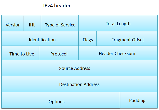
Let’s take a look at an IPv4 header.
There are three fields that we are specially interested in. Identification, flags and fragment offset. The identification field is used primarily for identifying fragments. Fragments which belong to the same original IP datagram will have the same number in the identification field. The flags field has three bits.
  • Bit 0: Reserved; must be zero (Sometimes referred to as the evil bit, see RFC 3514)
  • Bit 1: Don’t fragment bit
  • Bit 2: More fragments bit
If bit 1 is set, fragmentation is not allowed. This is useful for finding out the max size payload we can send. Bit 2 is set to indicate more fragments. All fragments that belong to an IP datagram will have the more fragments bit set except for the final fragment. This is so the end hosts can know when it has collected all the fragments of the IP datagram. The fragment offset field specifies the offset of a fragment. The first fragment will have an offset of 0. The next fragment will have an offset of 1280 if MTU = 1300 is used.
To verify that the max size is 1272 I will ping a host with a payload of 1272 bytes and the DF flag set, 1273 bytes will fail.
The ping is successful. This is what the packet looks like:
The frame is 1314 bytes long (1272 + 8 + 20 +14).  (Data:1272 + Ethernet Preamble:8+IPHeader:20+Ethernet Header14)
Total length = 1300 ( 1272 + 8 + 20). The DF bit is set, bit nr two of the flags field. We can also see the ICMP header further down. Now let’s see when we try to use 1273 bytes:
The frame is not allowed since it is too large.  Now lets generate some fragments, we will ping with a payload of 2544 bytes. This should generate exactly two frames.
Lets take a look in Wireshark:
Notice the identification field (17987). Also notice that the more fragments bit is set and that the fragment offset is 0. This is what the following frame looks like and it contains the actual ICMP header:
The identification field is the same (17987). The more fragments bit is not set since it’s the last fragment. The fragment offset is 1280. The first frame had 1280 bytes of data. This post should give you some insight to IP fragmentation. In a following post I will talk about TCP MTU discovery.

Cisco Doc: http://www.cisco.com/c/en/us/support/docs/ip/generic-routing-encapsulation-gre/25885-pmtud-ipfrag.html

Thursday, May 8, 2014

STP.RSTP.Uplink Fast. Backbone Fast.

Explanation for Uplink Fast

http://www.cisco.com/c/en/us/support/docs/lan-switching/spanning-tree-protocol/10575-51.html
The goal of uplink fast is to immediately forwarding for the alternate port

Backbone Fast
http://www.cisco.com/c/en/us/support/docs/lan-switching/spanning-tree-protocol/12014-18.html
It speed up the STP converge while the indirect link failure to the root.

Both uplink fast and backbone fast is to speed up the STP recovery time.

For the RSTP, it has this two similar features built in.

https://supportforums.cisco.com/discussion/11152846/rapid-pvst-uplink-fast-backbone-fast

There seems to be an ongoing misunderstanding about the relation of BackboneFast and UplinkFast to RSTP.
The RSTP alone, by itself, has built-in mechanisms that provide a similar functionality to Cisco's proprietary BackboneFast and UplinkFast STP extensions. Therefore, activating the RSTP (or the RPVST/RPVST+) immediately gives you the advantages of BackboneFast and UplinkFast. However, the BackboneFast and UplinkFast themselves are distinct extensions and they are not activated along with RSTP. In fact, even if you configured them together with running RSTP, they would not be active because RSTP already provides their functionality, although by slightly different mechanisms. That fact is confirmed by your output of show span sum
To sum it up, the RSTP already incorporates the functionality of UplinkFast and BackboneFast (although not implemented exactly in the way the UplinkFast and BackboneFast implement it), and when you activate RSTP, you get UplinkFast-like and BackboneFast-like functionality. The UplinkFast and BackboneFast alone, however, are not and will not be activated.

Thursday, September 20, 2012

INE Lab 1 Section 1.6


1.6  Disabling DTP Negotiation 
•  Disable Dynamic Trunking Protocol on the trunk links of SW1. 
•  Verify that trunking is still occurring between SW1 & SW2, SW1 & SW3, 
and SW1 & SW4 without the use of DTP. 

Still very confusing about the DTP mode. Google search and found the DTP relationship table. Below is the mode that able to form the Trunking Mode.


switchport mode access -  This command puts the interface (access port) into permanent nontrunking mode.  The interface will generate DTP frames, negotiating with the neighboring interface to convert the link into a nontrunk link. The interface becomes a nontrunk interface even if the neighboring interface does not agree to the change.

switchport mode dynamic desirable  - This command makes the interface actively attempt to convert the link to a trunk link. The interface becomes a trunk interface if the neighboring interface is set to trunk, desirable, or auto mode. This is the default mode for all Ethernet interfaces.  If the neighboring interface is set to the access or non-negotiate mode, the link will become a non-trunking link.


switchport mode dynamic auto – This command makes the interface willing to convert the link to a trunk link if  the neighboring interface is set to trunk or desirable mode.  Otherwise, the link will become a non-trunking link.

switchport mode trunk – This command puts the interface into permanent trunking mode and negotiates to
convert the link into a trunk link. The interface becomes a trunk interface even if the neighboring interface does not agree to the change.

switchport nonegotiate – Prevents the interface from generating DTP frames. You can use this command only when the interface switchport mode is access or trunk. You must manually configure the neighboring interface as a trunk interface to establish a trunk link, otherwise the link will be a non-trunking link.

Monday, September 10, 2012

INE Lab Physical Setup (part 1)

After getting 4 x Cisco 3550 switches, I am going to setup my lab using Ubuntu + GNS3.
I am following INE workbook. All the equipment are placed in the office's server room to enjoy 24 hrs air condition environment.

The equipment list as below.

1. i5 Computer with Ubuntu 12.0.4 installed. Cost around $500.
2. 12 x USB NIC Card (AX88772A Chip set). Each cost $5.
3. 2 x USB to serial converter. Each cost $2
4. 2 x 7 Ports USB Hub 2.0. Each cost $5. (one spoil :sad )

Equipment on the way: 2 x USB to RS232 converter.

As I am not familiar with Linux, it is difficult for me to do configuration.

The 1st problem I faced is the broken USB hub. Then since I am using USB-NIC solution, the Ubuntu cannot detect all the USB-NIC card. I plugged in one by one to make all the USB-NIC are in working condition.

Now I found out I cannot identify the corresponding USB-NIC to the mapping in Ubuntu.
I did some google and the solution as below.

* To see the USB logging in Ubuntu, issue "dmesg"


* To view the USB equipments list, issue "lsusb"


* To check the network connection, issue "ifconfig"


We can give the logical name to each of the USB-NIC. I am going to name them USB1, USB2.
To do this, follow the below steps.

1. sudo gedit
2. Open 70-persistent-net.rules which under /etc/udev/rules.d/
3. Change the key "Names = " USB1"


Few useful link:
https://alteeve.ca/w/Changing_the_ethX_to_Ethernet_Device_Mapping_in_EL6_and_Fedora_12+
https://help.ubuntu.com/10.04/serverguide/network-configuration.html